Eddie's Composting Loo fan
controller.
Click here for
version two.
 In
my Dalek loo page I wrote about a
range of options to improve the cost effectiveness of a solar
powered extraction fan for composting toilets. At the deluxe end
of the range was one incorporating a range of sensors including
temperature and humidity. Towards the miser end is the controller
I describe here. This controller has be built with one loo in mind
but may be useful to others. The loo in question is for a
community house at Nimbin rocks. The house has no permanent
residents and the average load on the loo is expected to be light
with a few peak usage periods every few months. The loo has
drainage so it is unlikely the fan needs to be run continuously.
The obvious times to run the fan are when someone is using the loo
and they want the bad smells to be prevented from escaping, the
other time is when we have plenty on power. The time you don't
want to run the fan is when the battery is running flat. As in
most solar electric (aka photo-voltaic) powered houses the
batteries are of the "lead acid" type and running them
flat is a very bad thing to do. (Later....The lid did not seal
well enough to stop bad smells coming up so I made
a two speed version)
In
my Dalek loo page I wrote about a
range of options to improve the cost effectiveness of a solar
powered extraction fan for composting toilets. At the deluxe end
of the range was one incorporating a range of sensors including
temperature and humidity. Towards the miser end is the controller
I describe here. This controller has be built with one loo in mind
but may be useful to others. The loo in question is for a
community house at Nimbin rocks. The house has no permanent
residents and the average load on the loo is expected to be light
with a few peak usage periods every few months. The loo has
drainage so it is unlikely the fan needs to be run continuously.
The obvious times to run the fan are when someone is using the loo
and they want the bad smells to be prevented from escaping, the
other time is when we have plenty on power. The time you don't
want to run the fan is when the battery is running flat. As in
most solar electric (aka photo-voltaic) powered houses the
batteries are of the "lead acid" type and running them
flat is a very bad thing to do. (Later....The lid did not seal
well enough to stop bad smells coming up so I made
a two speed version)
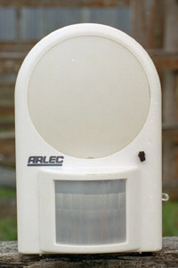
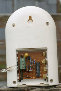
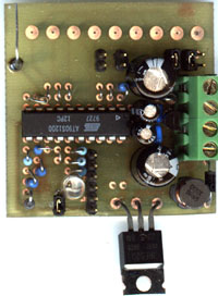
For this project I used an Atmel AVR series micro controller - the AT90S1200. This micro is a single chip computer - all it needs to run is a power supply. It contains an 8 bit RISC processor, 1 KiloByte of flash rom, RC clock source, timer, analog comparator, watch dog timer and general purpose I/O pins. The one I had on hand is faster than needed and cost $7 (we had to buy 14 or so - one tube full). I think the slower ones cost $3-$4. The flash rom is programmable via a serial peripheral port (SPI) port so the chip can be programmed in circuit. Since almost everything is done in the micro the circuit becomes trivial. A 7805 style regulator provides power, 6 pins interface the SPI port to a programmer, an output pin drives a MOSFET which switches power to the fan, some resistors sense battery voltage and one input pin interfaces to a Passive Infra-red (PIR) detector. The PIR detector I used is a battery powered Arlec sensor light. This cost around $22 aus and normally runs off four AA batteries - nominally 6 volts. With the bulb removed the power consumption was quite low. It also runs quite happily on 5 volts. The units has a light detector to prevent the lamp turning on during the day. I disabled this by poking some black foam into the hole the light sensor looks through. I rewired the inside of the sensor unit so that I could insert the controller into the battery compartment and interface the sensor and controller via some of the battery contacts. The sensor was powered by the controller's 5 volts supply. The wire which normally goes to the back of the lamp produces a nice signal for the micro, the signal lasts for 15 seconds from being triggered. The 5 volt supply also powers the programmer. The power supply is a low power 7805 device, this is a cheap fixed voltage 5 volt linear regulator. The nominal 12 volt supply from the battery passes through a reverse voltage protection diode and is filtered by a capacitor (say a 22 uF Tant), the regulator output has a .1 uF ceramic capacitor on it to improve stability. The micro can run on a lower voltage supply but 5 volts is needed during serial programming to generate the correct clock speeds etc. A 5 volt supply also provides the AVR output pin with plenty of voltage for the switching the MOSFET. I doubt it's worth the trouble of setting up a low voltage supply to save a few milliamps of standby current. The MOSFET gate is driven via a resistor and a zener protects against high gate voltages. The zener may not be needed but at 30 cents its a cheap precaution. The MOSFET is run way below its current rating and should not need a heatsink. The micro has one analog comparator. I used this for sensing battery charge state. The battery voltage does not give and accurate indication of the state of charge because we don't know the load on the battery, the voltage drop in the wiring or the battery temperature but setting up an under voltage and high voltage threshold should be huge improvement over no battery state feedback at all. A resistive voltage divider consisting of two 10K resistors between an output pin (set low) and 5 volts gives a reference voltage of about 2.5 volts. It's a little over 2.5 volts because the output doesn't pull down to zero volts but it's close, this goes to one comparator input. A second divider consists of a 10K resistor going to the cathode of the reverse voltage protection diode. Two different resistors go from the other side of the 10K resistor to 2 output pins. One of the two outputs is brought low to change the divider ratio. The pins are never driven high - they are either low voltage or high-impedance. The second divider goes to the second comparator pin. I was aiming to sense thresholds of around 11 and 13 volts. In the prototype this turned out to be around 11.3 and 13.3 volts which is close enough for now. Obviously I could have used trimpots to adjust the thresholds but fixed resistors are simpler, cheaper and won't be fiddled with by people who don't know what they're doing (myself included). The second comparator input also has a zener diode to clamp the voltages within safe limits in case both output port pins go high. Again this may be unnecessary because the outputs probably have internal protection diodes. Minor power savings could be made by turning the dividers off when they're not needed and also by increasing the resistor values.
The software is quite simple, it has to be because this is my first program for this type of micro. The internal timer is used to generate all the delays, it is not interrupt driven and simple delay loops could have been used but the timer is easy enough to use and in some future version of the program we may want to do something else during the delay period such as generate a pulse width modulated (PWM) output for fan speed control. The timer is set to it's slowest clock rate - the cpu clock rate divided by 1024. This is very roughly a millisecond per tick. The counter is 8 bits long so the maximum timeout period is (again very roughly) a quarter of a second. Both these delays values are used in the program. The main program loop starts with a test to see if the battery is flat. If it is - it turns off the fan and rechecks till it the voltage rises about 11 volts. If the voltage is above 11 volts it looks for an intruder signal from the PIR, if it finds one it turns on the fan and starts a five minute delay, while timing, the delay is reset to five minutes whenever the PIR signal is there. Hence the fan should run for five minutes after the signal goes away. If no signal was found the program checks if the battery is over 13 volts. If so it turns on the fan for a minimum of 1 minute (aprox). During this minute it checks for a PIR signal and if it find one the program jumps to the PIR delay routine (ie the five minute delay). If the 13 volts threshold was never detected the fan is turned off and the main loop restarted. This is all hard to explain so viewing the program source is a must if you want to understand it. When the prototype was hooked up to the community house electrical system we had some bizarre problems with the electric fence apparently resetting the micro every time the fence was energized. Even when the fence energizer was given it's own battery it would reset the micro under some conditions, there appears to be some sort of inductive coupling from the fence circuit to the house wiring. It's likely the controller could be made less sensitive to interference by improving the power supply filtering by adding more caps and some series resistance or inductance. We have a minor problem with positioning the sensor. This is mainly because the toilet shares the room with a shower/bath. We will possibly have the live with the fan coming on when people are using the shower but placing the sensor on the ceiling looking down may minimize this. Apart from those hitches it works! Well sort of.
Here
is the program Loofan.asm
Here is the
assembled code Loofan.hex
 While
version one worked as designed - the toilet lid did not seal as
well as I'd hoped. Here is my second attempt at a fan controller.
To confuse you more the PCB shown here is intended to be
multi-functional. Depending on how it is populated and programmed
it can control either a fan or a pump - maybe more uses will come
along. The basic idea behind this version is to be able to control
the power going to the fan. I'm hoping that running the fan at say
1/4 power will still be enough to control odors. Linear power
control devices are too inefficient so switched mode techniques
have been used. I also added a LED and jumper selectable power
control. The controller is similar to version one in many ways.
The same micro is used and pin functions have been kept the same
as much as possible. The version one program should still run on
version 2 hardware.
While
version one worked as designed - the toilet lid did not seal as
well as I'd hoped. Here is my second attempt at a fan controller.
To confuse you more the PCB shown here is intended to be
multi-functional. Depending on how it is populated and programmed
it can control either a fan or a pump - maybe more uses will come
along. The basic idea behind this version is to be able to control
the power going to the fan. I'm hoping that running the fan at say
1/4 power will still be enough to control odors. Linear power
control devices are too inefficient so switched mode techniques
have been used. I also added a LED and jumper selectable power
control. The controller is similar to version one in many ways.
The same micro is used and pin functions have been kept the same
as much as possible. The version one program should still run on
version 2 hardware.
Switched mode section.
A
tutorial on switch mode circuits is beyond the scope of this web
page. The switching circuit can be seen at the bottom right hand
corner of the schematic. It's consists of an inductor, flyback
diode, 2 caps and a power MOSFET. The switch components are also
in the bottom right of the PCB - apart from the large cap near the
top of the terminal block This circuit forms an "up side
down" buck circuit. Buck mode circuits usually produce an
output with respect to the negative rail. Mine produces an output
with respect to the positive rail. The reason for doing it this
way is to allow the use of cheap N-channel FET as the switching
element. The inductor would saturate in around 30 micro-seconds
but this is dependent on battery and fan voltage. The FET is
pulsed for 14 to 30 micro-seconds @ about 14 kHz when running the
fan at low speed. When high power is needed the FET remains on and
the inductor is allowed to saturate. Once saturated the inductor
and FET have minimal voltage drop across them (about 0.2 volts)
and the fan has almost the full battery voltage across it. The
switcher does not regulate. The system is an open loop - there is
no feedback. The low power mode should only be active when the
battery voltage is from 11 to 13 volts. The fan power will vary
with input voltage - approximately proportional to the
voltage difference between input and output squared. I think this
can be called a feature (MS would).
The FET is gated in
software. The Micro's counter overflow is used to generate
interrupts @ 14kHz. The interrupt routine uses a software delay
(not the counter) to generate the pulse width. The delay software
reads 4 jumper settings on the fly an varies the pulse width
accordingly. The gate resistor shown in the circuit has been
replaced with a wire link. I'm not using the gate protection zener
diode either.
Jumpers.
When use as a pump controller the zener
diodes and resistors hanging off port D bits 0 to 4 are used to
interface to level switches. In the fan controller the zeners are
replaced by jumper pins and the resistors replaced by wire links.
The jumpers are top in the PCB scan. The left jumper is
unused and the other 4 set the FET on time. The jumper on the
right is the least significant with each jumper increasing in
significance as we go left.
LED
The LED indicates the current power mode and
doubles as a night light. The LED flashes 1,2 or 3 times to
indicate - fan off, fan low power and fan full power. When the fan
is at full power because of a PIR trigger the LED remains lit for
the timeout period (about 2 minutes).
SPI
The SPI port is used to program the flash memory
in the micro. It is marked as "con1" in the schematic
and is visible between the LED and FET at the bottom of the
PCB.
Here is the source
code for mutlispeedfan.asm
and the
hex dump Mutlispd.hex
Dave Keenan has placed the circuit and program for an AVR programmer online at http://users.bigpond.net.au/d.keenan/AVR