 The
wiring diagram out of the manual is here.
The
wiring diagram out of the manual is here.
 The
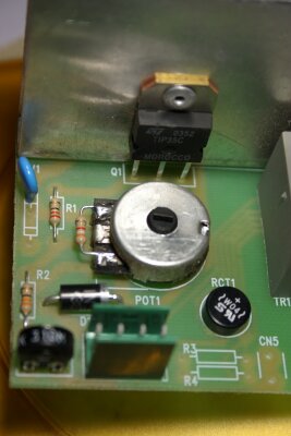
circuit board – not much too it. The rectifier (black round
thing bottom right) is not part of the speed circuit. The
trim-pot is the blurry black thing bottom left. The nut which
hold the pot is all that holds the PCB in place. There is a piece
of cardboard between the pcb tracks and the case – I think
that is pretty slack.
The
circuit board – not much too it. The rectifier (black round
thing bottom right) is not part of the speed circuit. The
trim-pot is the blurry black thing bottom left. The nut which
hold the pot is all that holds the PCB in place. There is a piece
of cardboard between the pcb tracks and the case – I think
that is pretty slack.
 This
is what I make the circuit out to be. The 3k9 resistor looks like
it was an add on. To make the welder work I had the trim-pot
adjusted to 40 Ohm (40R) this means the wiper is at one end of
the resistive track so all the heat is being generated in one
little spot. It also made adjustment very touchy and prone the
being changed by knocks. Because the trimmer was only 40R the
overall resistance from the motor to the transistor base is under
100R but there should only be about 0.6V across this so the
current should only be 6mA and power dissipation in the trimmer
only 3.6 mW.
This
is what I make the circuit out to be. The 3k9 resistor looks like
it was an add on. To make the welder work I had the trim-pot
adjusted to 40 Ohm (40R) this means the wiper is at one end of
the resistive track so all the heat is being generated in one
little spot. It also made adjustment very touchy and prone the
being changed by knocks. Because the trimmer was only 40R the
overall resistance from the motor to the transistor base is under
100R but there should only be about 0.6V across this so the
current should only be 6mA and power dissipation in the trimmer
only 3.6 mW.
The circuit is powered by full wave rectified DC and not pure DC so some of the time there will be less current flowing.
At a glance I got that wrong first up and thought there was more voltage (and current). The big voltage is across the main pot and not the low valued resistors.
So I replaced the trimmer with a 200R of fixed resistance in parallel with a 100R trimmer. This works fine but the trimmer alone would probably have done. The idea behind the extra resistors was the take some of the load off the trimmer. It will also make the adjustment less sensitive and this is still a good thing as long as you don't run out of range. The values you can get trim-pots in are fairly coarse so adding some extra resistors is not uncommon. I had very little choice at my local electronics shop 100R trim pots were about all I could get in the right package.
 When
you lump all the resistors together the circuit looks like this.
It acts like a big (adjustable) zener. The resistor (pot) ratios
set the voltage at which the circuit conducts – it drops a
fixed voltage and what is left is across the motor. It doesn't
regulate the motor (M) voltage as such. If the power supply
voltage changes the motor voltage changes. It is surprising that
the motor speed matches the tip voltage as well as it does.
When
you lump all the resistors together the circuit looks like this.
It acts like a big (adjustable) zener. The resistor (pot) ratios
set the voltage at which the circuit conducts – it drops a
fixed voltage and what is left is across the motor. It doesn't
regulate the motor (M) voltage as such. If the power supply
voltage changes the motor voltage changes. It is surprising that
the motor speed matches the tip voltage as well as it does.
The bottom line is - so far so good. I've done a few hours welding and the speed control is much better. The MAG welds I did were a lot better than last time but I still went back to using MOG and it worked fine.
May 2007.
I have never said that other welders have this problem but
several people have emailed me to say they had the same thing and
this mod fixed it.
There is clearly more than one way to fix
it.
As I say at the top don't mess with this if you
don't know what you are doing.
Any experienced repairer will understand this page. If it
doesn't make sense don't attempt the mod – find someone
more able.
This is not a “learn electronics” site,
I won't be walking people through the repair.
Several people who emailed me clearly should not be taking the covers off their machines.
I've been expected to remotely diagnose other models (which
I've never seen – inside or out) with little more that –
it's broke.
I've been expected to drop whatever I've doing to
give free advice and even received a nasty response from one guy
when I've declined.
I was later informed by this same guy that
an engineer had fixed his welder by changing a “three
legged fuse” on the heat sink.
I'm quite sure he was not
joking, it was not intended to be a humorous email.
This
engineer sounds like my kind of guy :)
Many other engineers
have now had a good laugh.
I don't usually make fun of people
but this time it is well deserved.
If you don't get it -
google “three legged fuse” (including the quotes).
I was also told this welder had a 200R trimmer - so if it was a similar PCB, it was fitted with a more appropriate value trim-pot than mine.
EKM