My paraplane design.
The Black
Rainbow.
Note that there is video of the successor to BR on Nerdipedia.
|
31-May-2006 I want to design and build my own model paraplane. There are already designs out there but I want to do something a little different. Chutes look cool and are fun to fly but my model will be made as payload lifter. My primary payload will be a 120 gram 5 mega pixel digital camera. I'm planning on
having a payload pod which - like the one on thunderbird-two –
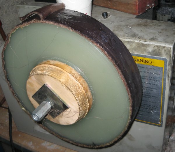
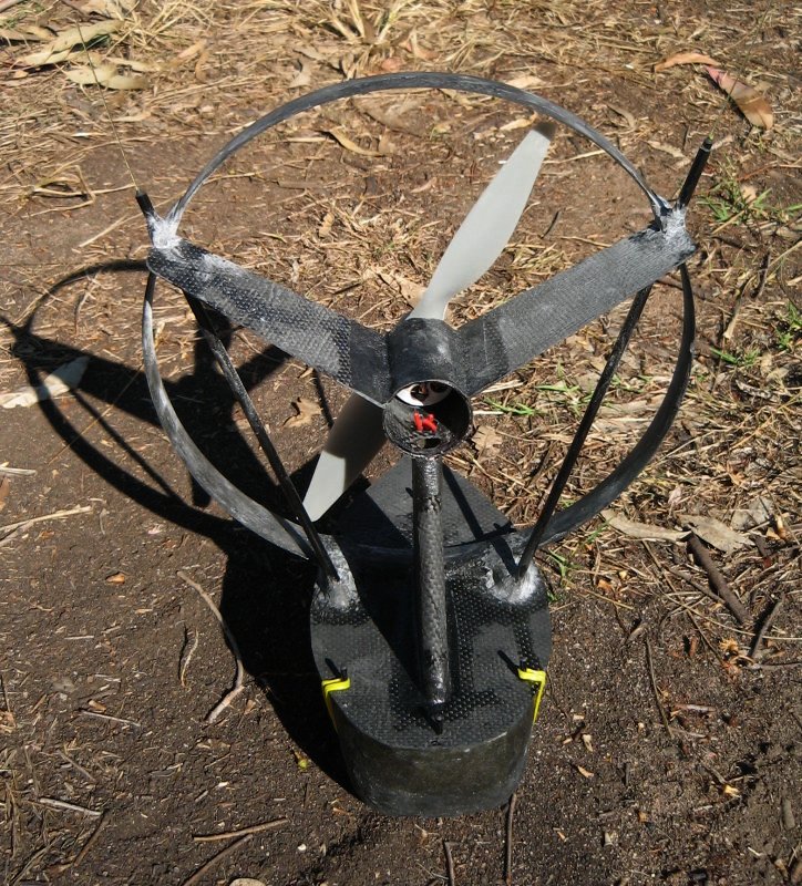
can be changed for different needs. Wheels will be optional. Some experiments still need to be to be done to finalize the design but I've made a start – I made the propeller shroud. This project started with a trip to “Crazy Clark's” to buy a kilo or two of cheap candles. I also had a measuring stick in my pocket – a 230 mm length of bamboo skewer – just in case I found a convenient round object I could use instead of wax. The cyber-chute propeller is 230 mm and I'd like to used the same size for the new beast. I came home and
melted some of the candles in a rice cooker – the small one
I use for melting wax – not the one I cook in. More wax was melted and poured into a round Chinese food container. I could have found
a ready made former to make my shroud around but carving wax is
more fun. I G-clamped some
steel to the bench frame to steady my hand and carved the
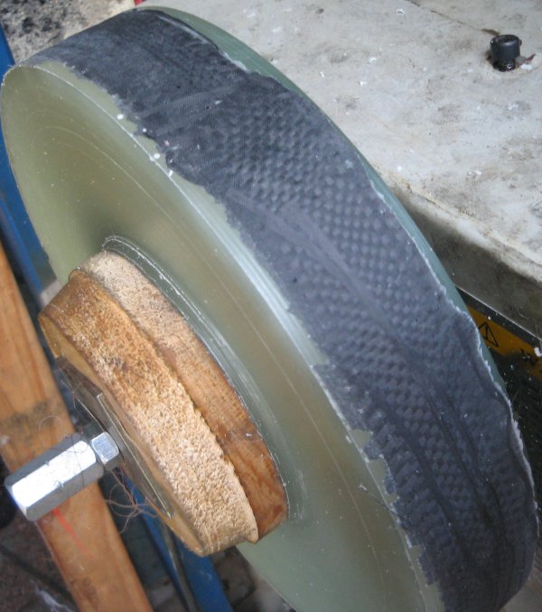
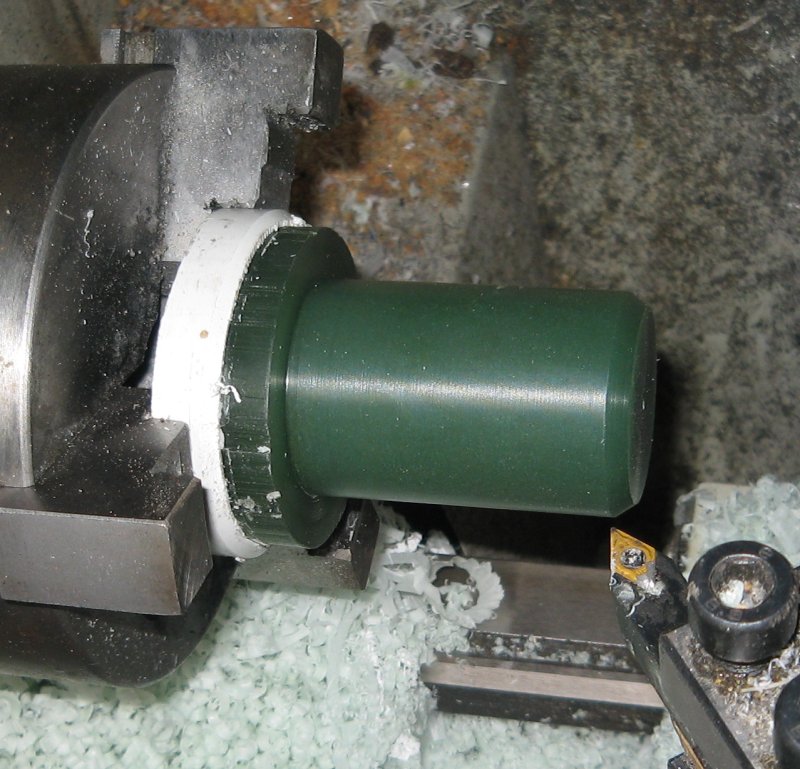
spinning block free hand. I laid the carbon
without removing the block from the lathe, I was hoping it would
remain in position so I could grind it round after it had
cured. For those who don't know – what should happen is the binder dissolves so the fibres are free to move and conform to the mould. A good example of this is glass fibre chopped strain mat (CSM) has a binder which dissolves in polyester resin – this works well. However if you use CSM with my epoxy the binder doesn't dissolve and the matt won't conform like it should. Later tests found
that acetone will dissolve the binder so it is possible a small
amount added to the epoxy might have worked – I'll need to
test this some time. |
|||||
|
|
|
|
|||
|
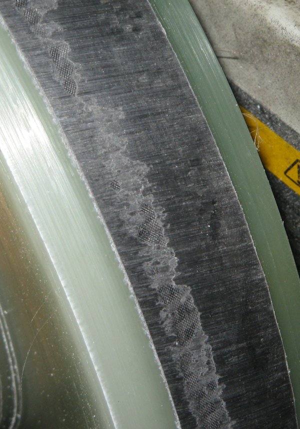
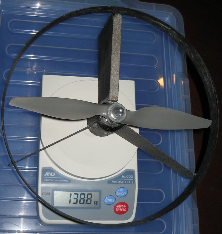
Most times when I use a wax mould like this I melt the wax to free the piece. This time however I just spun it and parted the shroud and 10mm of wax from the rest of the block by using a 2 mm CF rod as a parting tool. Once separated the wax was easily broken and removed from the CF shroud. The shroud ended up 240 mm ID, about 2mm thick and 21mm wide – it weighed in at 38 grams and is just what I had in mind. I also
noticed my big rice cooker- the one I cook in and don't use for
wax – is almost the perfect size to use as a former to make
a shroud like this. I'd have a wrap a few layers of tape around
to build it up a little and the result wouldn't have the same
profile but it would work. I ordered a motor on the weekend from
http://www.gobrushless.com
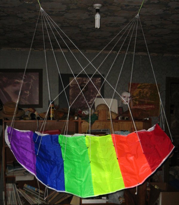
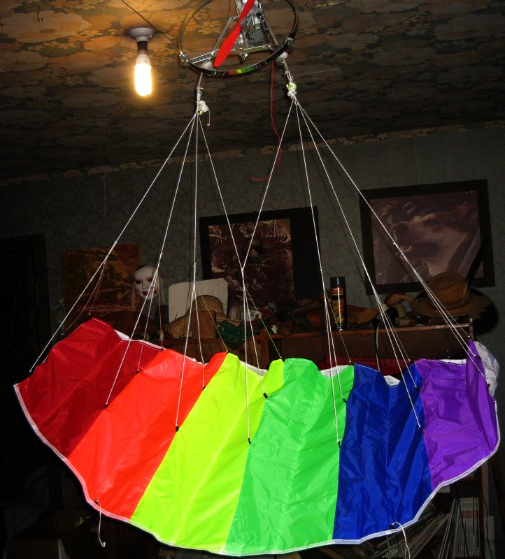
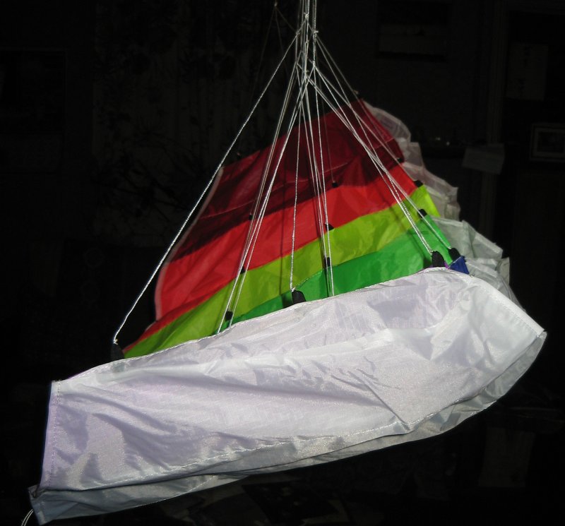
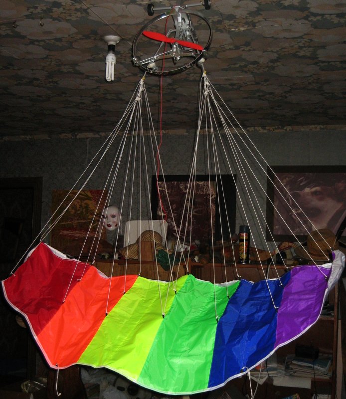
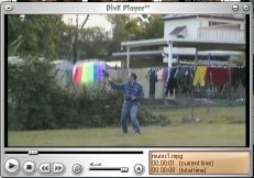
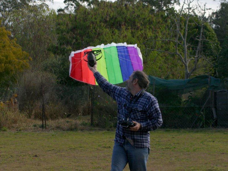
9-June. The “rainbow stardust” kite arrived so there was a detour to see if it works. |
|||||
|
|
|
||||
|
|
|
||||
|
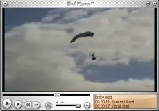
After I shortened the
lines I moved the main arm of the cyber-chute gondola back a
little, attached the kite and tried to fly it.
I didn't know what line lengths to use and too a guess. I had too much AOA first up but it was well behaved, it refused to climb and just floated down and landed. The server pull to the right was also gone. The best results I had were with the front lines 78cm second 80 and rear 84. With these lengths it would start to climb then give up and come down again.
This behaviour was a mystery until I measure the static thrust. It was also 300 grams but decreased rapidly by almost a third. Apparently I'm overloading the battery.
I'm sure this will fly but it obviously needs more power than the plastic cyber-chute canopy. I'm not sure exactly why. It is a little heavier but the overall weight is pretty much what it should be. More power may just be the price to pay for using a cloth chute.
14-June.
Back to building. It took three attempts to make the motor mounting tube. First time it got too hot and the wax plug melted. Second time the CF looked OK but I accidentally cut through the side when I was trying to tidy it up on the lathe. On the third try I did a vacuum infusion of the resin instead of a wet layup and this was much easier and less messy. There was a problem machining it because I had a nice inner surface but nothing much to hold it straight in the chuck. So I made a matching plug out of cured epoxy which I could hold in the chuck and press the tube onto it and turn it with some accuracy. The end product weight in at 11 grams but a little more was removed later and there will be ventilation holes drill. This should shave another gram or two off the weight. |
|||||
|
|
|
||||
|
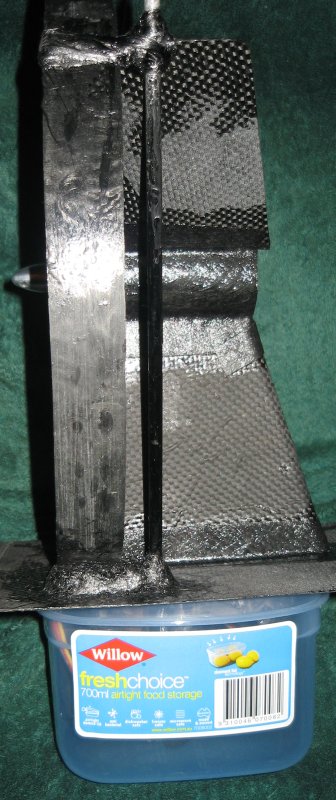
The main fin is made from 10mm PVC foam covered with one layer of 200 GSM carbon – a single piece. This was also vacuum infused. Embedded in the leading edge is a 10mm CF tube for running wires up to the ESC. The resin gelled before the infusion was complete but I managed to add more resin and finish the job without any visible defect in the finished piece. After trimming to size, some foam was removed from the inside of the top of the fin to allows the motor wires to be brought back to the ESC on the outside of the tube. Since the motor is an “out runner” I need to keep the wires away from the spinning can, so it is easier to take them past on the outside of the tube and inside the fin. The two upper fins are
sheets made from 4 or 5 layers of the same carbon cloth.
July-7-2006 Steering. The top common steering mechanisms that I know of are a “tilt bar” and the system used by the sky surfer and it's clones. I don't like tilt bars because they will get damaged when a crash occurs. I think the surfer systems is better in this regard but I though I could do even better by putting the main mechanism below deck where is is well protected and bring lines topside inside strong CF tubes. I thought about
different ways to do this and decided to use a servo controlled
pulley with captive control lines. The first is it that
it has a linear relationship when converting rotary to linear
motion. By this I mean one degree rotation will produce the same
amount of travel in the line regardless of the amount of
deflection. On the other hand the servo arms on the sky surfer
will have the greatest travel per degree when the controls are
level – this is when you want the finest control not the
coarsest, this could be compensated for the electronics. The sky
surfer's arms move in and out as well as up and down so it isn't
that simple.
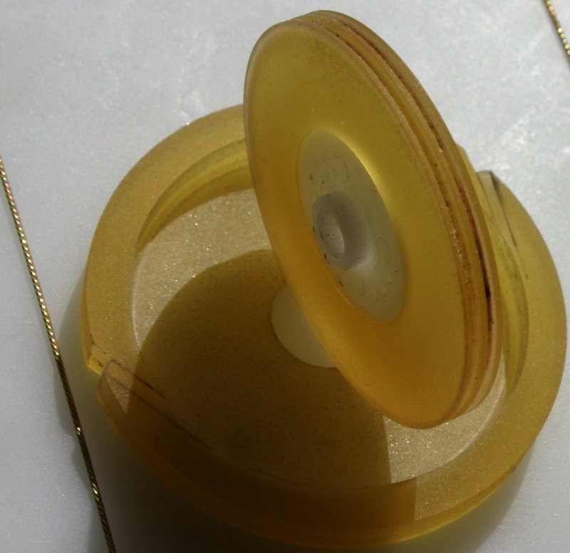
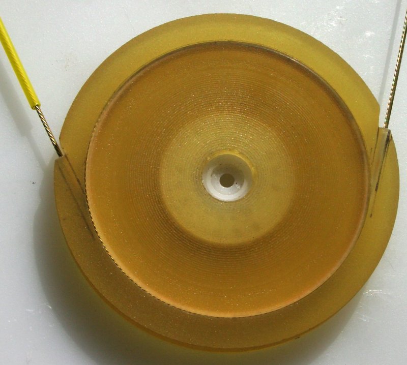
My pulley was another case of a practice piece turning out good enough to use. I didn't have any suitable stock material to use so I poured some epoxy resin into various containers to make rods and disks of various sizes. I found my wax bath is excellent for post curing. It takes many days for resin to cure. It will turn solid fairly rapidly but doesn't reach maximum strength for quite a while. This resin splinters if machined with a day or two of setting but a few hours sitting in 120 deg C wax makes it really hard. The pulley is 50mm in
diameter with two groves which are just deep enough to hold the
cable. The cable is gold-n-cable #507 - this has a brass plated
stainless steel cable approx 0.8mm in diameter plus a low
friction nylon sleeve.
|
|||||
|
|
|
||||
|
So I figured that if it can pop out I can make it pop in too. It was very easy to put one wire in this way. I bent the wire ends 90 degrees and glued them in place. Putting one wire is easy but two wires is not possible. So the trick is to make the wire on the right in the photos pass through a slot instead of a hole. The slot was made the correct size to take the sleeve and this side will mount up against servo bracket making it a snug fit. July-16'th, The bottom part of the paraplane is an
interchangeable payload module but for testing all that is
required is a protective shell. The skins of the future module
will be vacuum infused carbon or kevlar. I have already cast a block of wax to carve the plug for the camera module but wanted something quick and dirty for the test flights. I looked around for something I could use to make a pattern and found some plastic containers at the supermarket. I bought everything that looked about the right size and choose the best fit at home. One of the containers was close to being the correct size but need to be spread a little. Some pieces cut from a fruit bottle gave it the extra size and shape I needed. It ended up looking a bit like something from a montie-python movie but it will do. |
|||||
|
|
|
||||
|
|
|
||||
|
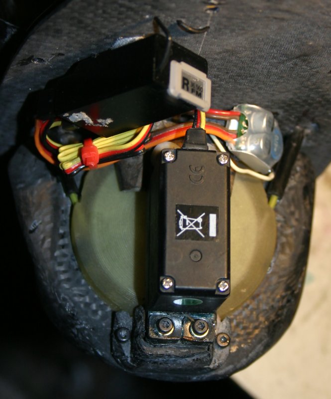
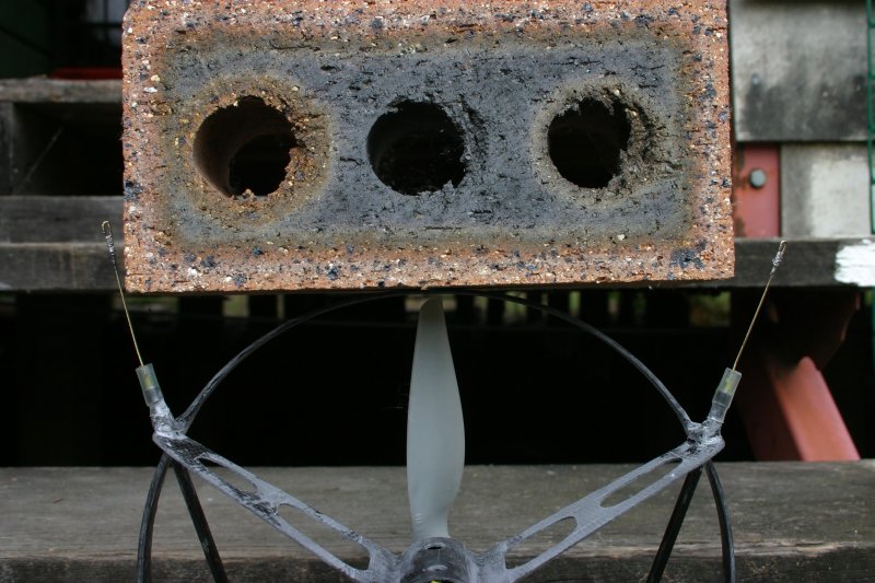
July 19'th Next the CF tubes for the gold-n-cable where trimmed to length. Flexible tubing and heat shrink were attached to help protect the wire against kinking in the case of a crash. The ends of the wire were bent back, bound with fine copper wire and soldered. This provides a good attachment point for a brass swivel. A pheonix-10 brushless ESC was recycled from the carbon-sixty project and initially connected to the motor with clips so I could make sure the motor direction was correct before soldering. I hung the model from two strings hooked to the ceiling. The thrust when powered by a two cells LiPo was disappointing. The power to weight seems worse than the stock cyber-chute. Using three cells make a big difference but it still isn't spectacular. There was a gondola stability problem. This didn't surprise me too much. The gondola would oscillate from side to side, sometimes quite violently. Adding weight or reducing power definitely helped. For comparison I suspended the cyber chute gondola the same way and it was much worse so I figure it won't be a problem when attached to a real chute. I soldered the motor directly to the ESC and ran three wires down the inside of the fin. Normally you'd expect five wires. Because I'm not using the BEC on the ESC (in other words I'm not using the ESC to provide 5 volt power) I don't need the two 5V power wires. I only need the two battery wires and one signal wire for the throttle. The ESC was hot glued in place. To supply 5V for the radio and servo(s) I'm using
a switched mode park-BEC. This plugs into the radio's ESC
channel. |
|||||
|
|
|
||||
|
|
|||||
|
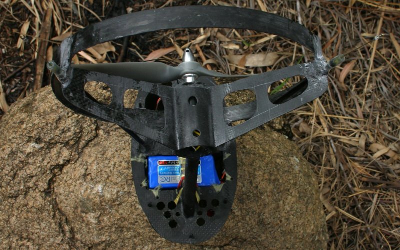
The weight was pretty
much what I expected but the empty cyber-chute gondola is lighter
than I realized. My lift module alone (no shell) is 48 grams
heavier than the cyber-chute gondola.
I got the weight down
to 302 grams and stopped. The bottom shell still heavy but this doesn't matter because it is temporary. With the lighter weight and my new three cell 1040 mAh battery I think I have over a 1:1 power to weight ratio on the gondola with it's shell.
I bought a “blue-bird” brand servo that looks like it will be up to the job and is 30 grams lighter! Just to make life difficult the spline on this servo is a little bigger than the hi-tech one. If I can't make it fit it will take a complete disassembly of the steering gear to replace the servo wheel. I choose not to replace the servo for the test flight and laced the servo mount in place instead of gluing and left the servo just tacked in place because it is all coming out ASAP.
|
|||||
|
|
|
||||
|
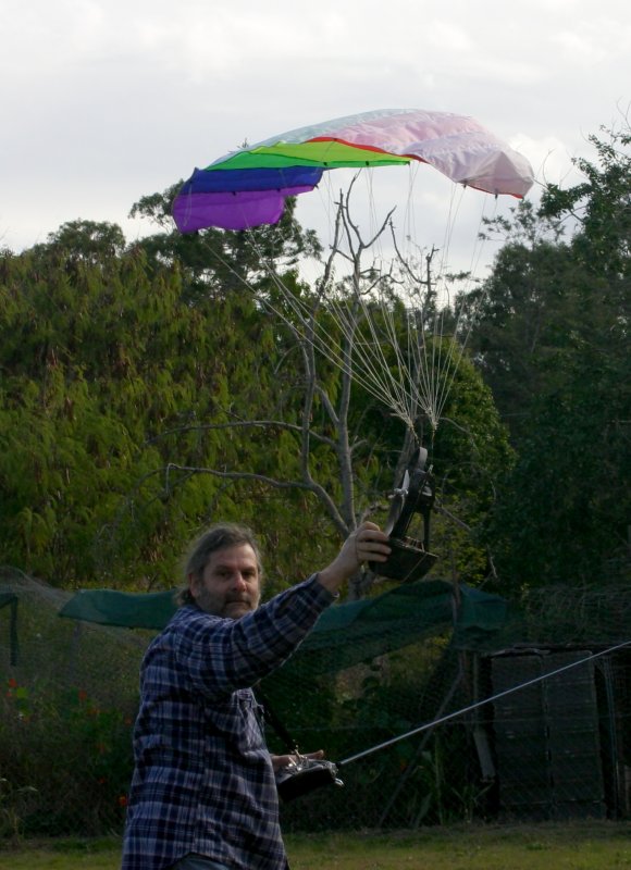
I
had no doubt now that this thing could fly :-)
Then
I lost it, it turned down wind. I may have reserve controls and
steered to there, I'm not sure. It was on a nice stable glide
into the neighbours yard and I didn't try to stop it because I
would have ended up on the fence. One rubber band broke but the gondola shell was still in place and undamaged but the that poorly secured steering assembly broke loose and that was the end of the test flying – but it flew and that's a good thing. I'd even say it flew well.
|
|||||
|
|
|
||||
|
As I said earlier, if you just want a working
parafoil there are easier ways to do it. I did this because I had
some ideas I wanted to try out. If I built another one I'd
possibly do it differently but until you try building one, it is
hard to imagining exactly how things will work out. I had to take
a lot of guesses and some were a little off. I've put a ridiculous amount of time into this and will be reducing this to work on other things. Before building the camera payload module I'll be
improving my
vacuum infusion techniques. |
|||||
Cheers Eddie.M.
My models page is here and my home page is here.