Fighting the
Epson ink chip and winning!!
Or how to
void your printer warranty on the internet.
Started22/09/02
This project continues at http://nerdipedia.com
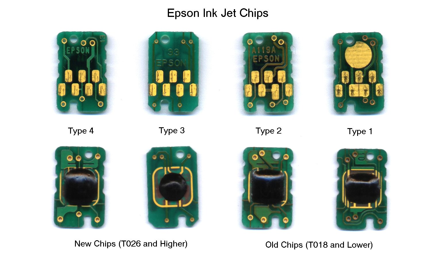
What is a Intellidge ink chip.
Epson fit
small circuit boards to most of their ink cartridges. These
record the amount of ink that is estimated to be in the
cartridge. I read that the official epson line is that it is for
the customers benefit and not an anti-refill device. Whether you
believe this or not they are a bloody nuisance to anyone wanting
to refill the cartridges or use bulk ink. It also stops people
using old cartridges full of solvent for cleaning the heads.
Another problem was early printer models didn't check if the
cartridge had been changed while power was on. This was good if
you wanted to trick the printer into copying a “full”
chip to and empty one, however the reverse was also true and you
could easily copy and “empty” one into your full
one.
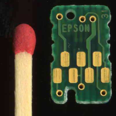
They are just a small memory device holds 32 bytes of
data, they do not measure real ink level and nor does the
printer. The printer reads the chips on startup, estimates
(sometimes badly) how much ink should have been used and writes
this back at shutdown. They hold other data as well.
So epson
go to the trouble of fitting chips to cartridges and building all
the extra sockets, wiring, electronics and software into the
printer so you can use the computer to see the predicted level
and it can stop you printing if it think you've used enough ink.
High-end Canon's on the other hand make the inks tank clear so
you can see and have optical sensor to detect emptiness. This
make a lot more sense – unless you are making an
anti-refill device that is. Canon almost got my business this
time but nobody I could find has run pigment in them – too
risky.
To get around the chip problems someone usually end up
producing read-only chip which always read full (for use with
CIS) and chip reseters for those who want to refill. These are
not available for 2100p at the time of writing as far as I can
tell.
Before ordering my 2100p I did my homework and it seemed
fairly likely a chip reseter would become available at some point
and read-only chips as well. I was also cocky enough to think I
could crack it myself and I have. It didn't go quite as expected
though.
What do I want to do?
I want the easiest way
to fool the printer into believing it has full cartridges present
so I can build my CIS.
What did I expect?
A logical
interface for Intellidge is i2c (i squared c) or TWI (two wire
interface). Then the chip could just be some standard i2c eeprom.
The Intellidge have too many pads for this but I was hopeful.
After that would could SPI or microwire – again this could
use off the shelf parts. If the chips were micro-controllers then
plain asynchronous serial would be my choice.
I had a
look.
To do this I use a AVR mega323 micro, I declined
offers of logic analyzers being a homebrew type of guy. The 323
has 2K of internal ram which is enough for some minimalist data
logging. It was about $50AUS in parts ($30US) to make. I wired a
cartridge to bring the signals out and took a quick look with a
voltmeter.
Nothing!
There was nothing there. I
expected some power but no, the chips are only powered briefly
when the are accessed. I used leds to get a rough idea what was
what and hooked up the micro via resistors to give some degree of
protection to the printer if I screwed up. The code in the micro
was written is assembler and captured data sent via rs232 to my
PC where I wrote a delphi program to display and process the
data.
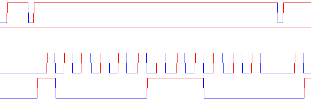
This is the sort of thing I got. No
protocol I ever seen. Obviously synchronous with bi-directional
data, very short format. I was confused a little by how short it
was - because I expect much better precision for the ink
level.
The traces seem to be.
Top – some sort of sync
line, this always goes low before the start of transmission.
Next
– power this goes low (off) between chip reads at printer
startup but stays high during the shutdown – when data is
written to the chip.
Next – the clock, data is read of
the rising edge and changed on the falling.
Bottom –
bi-directional data, the first 4 bits are always from printer to
the chip, the rest depend on whether it is a read or write. LSB
first (left).
Convert to binary and some patterns emerge.
It
was not real obvious how the chips were addressed or which bits
encoded ink levels. Some more data when some ink had been used
made it easier.
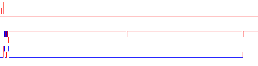
Below is one chip being read at startup, there are 7 accesses one for each chip. Only 3 block have data – the other chips must be hooked to different data lines.
![]()
Below is the complete shutdown stream. Again we can only see 3 chips from here.
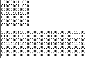
After
printing a few bits near the beginning of the bit stream did
change. It looks to me like the first 3 bits are the chip address
the next is a write bit then the ink level, I get the feeling
there aren't many bits used to encode it (later looks like 6).
So
– the top one shows 252 bits of data being read out of the
chip.
The first part of the shutdown shows just the ink level
being read out, this is to check the same chip is there.
The
second part is the ink-level and some other stuff (printer serial
number maybe) being written into the chip. Seeing I didn't use
any ink the bit-stream is identical to the read except for bit 3
– presumably the write bit.
Tuesday
24 Sept 2002. I fooled the printer.
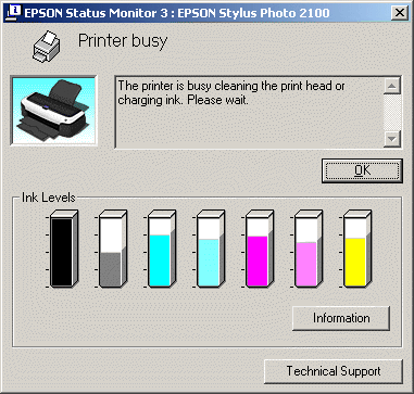 The
interesting thing about this screen grab is the black cartridge
is really only two thirds full. I spoofed the printer by pulling
the serial data line low during the time the ink level bits are
being clocked out of the ink chip.
The
interesting thing about this screen grab is the black cartridge
is really only two thirds full. I spoofed the printer by pulling
the serial data line low during the time the ink level bits are
being clocked out of the ink chip.
This is means 6 bits
starting at the 5'th bit in the stream.
The first 3 bits appear to be the chip address, I guess the next is a read/write select. I used a AVR mega323 to detect the start of the serial transmission look for the address of chip1+read (black apparently) then pull data low for 6 clock edges.
I'm sure I can reset 3 of the chips by tapping into chip1 signal. Reseting the rest will mean tapping into at least one more.
The current set up is for experimentation only – it is not “the real thing”.
Shorting the data to ground may be a bit drastic but it is only for a very brief time. I hoped the data line would be open collector but this doesn't seem to be the case.