Micro based PIR to IR remote
converter.
(An Atmel AT90S1200 controlling
a panasonic VCR)
There is also companion ir-cctv
page.
After the third attack on my car in 6 weeks, loosing 35 litres
of fuel and generally having my day stuffed up - I got really
pissed off and embarked on the EKM-1 surveillance camera system. Next time I
want to get the act on video. My first thought was to keep it
simple and use a PIR (passive Infra-red) motion detector to set
off an alarm in my bedroom - then I would manually start my VCR
and record video from a low-light
camera. I got carried away and built an automatic system which
starts the VCR recording and stops four minutes after the last PIR
event. The only practical way to do this is via the IR (infrared )
remote control sensor. There was a kit available which used a
dedicated "learning" remote control to send the record
and stop code but this seemed a bit crude and expensive. Mike
pointed me to the www.hut.fi/Misc/Electronics/opto.html
web page. Here I found lots of interesting stuff includingfalcon.arts.cornell.edu/~dnegro/IR/REMOTES/PANASONI.HTML
which had the control codes, modulation and encoding protocols for
panasonic VCRs - which is what I have. I was half way through
another micro project - a pump controller when IR remote
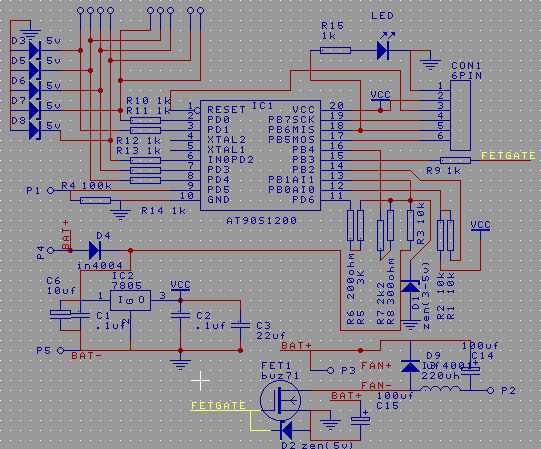
control gained priority. The pump controller schematic looks
something like this. It's a multi-purpose PCB which also works as
a loo-fan controller. For the
pump controller a couple of zener diodes in the switch scanning
inferface (top left) have been replaced with 1uF caps and the
inductor and catch diode (bottom right) are left off.

Anyway,
that's what I was doing. So I replaced the gate resistor with a
link to improve the FET switching time and hung both a
visible and IR LEDs where the pump would go. I remove the water
level sensing switches and vola! the hardware was ready. This
circuit has a lot of unused parts. A power supply, a micro, an IR
LED and a resistor is all that's needed for a low power IR code
transmitter.
Now the software -
The panasonic remote control system uses
a 48 bit control code consisting of a 32 bit group identifier -
the code for VCR functions is hex 40040900. This is followed by a
16 bit function code such as hex 0009 for "STOP". So the
48 bit VCR STOP code is hex 400409000009. The code is
transmitted most significant bit first. I suspect they'd make more
sense if reversed and sent LSB first but I'll leave the codes
as I found them. Each bit is encoded as a modulated carrier pulse
"T" long followed by a period with no carrier. One "T"
period for a low bit or three "T" periods for a high
bit. The "T" period is nominally 400 micro-seconds -
more on this subject later. The carrier frequency is 32 kHz. So a
"T" burst consists of around 13 pulses of IR with a
period of 31.25 micoseconds each - 31 is near enough. Getting
32kHz out of a micro port pin in software is hardly rocket
science. For a AT90S12 running at 1 meg my code looks like
this.
IRon and IRoff are macros which equate to "sbi
PORTB,PB3" and "cbi PORTB,PB3"
This bit of code
sends one burst of 32kHz pulses for around 400 micro-seconds.
; IR pulsing routines Tpulse: ; a series of 13 cycles with 16
uSec on and 15 uSec off.
ldi
counter1,13 ; 1 cycle ; led on time = counter2*3 + 2 + 1 + 1 + 1 +
1+1 = (C2-1)*3+7
TPloop: iron ;
2 cycles
nop
; 1 cycle
ldi
counter2,4 ; 1 cycle
TPondel:dec counter2 ;
1 cycle decrement counter
brne
TPondel ; 1 or 2 cycles - and loop more if not
zero
ldi
counter2,4 ; 1 cycle ; led off time = counter2*3 + 2 +
1 + 1 + 1 +1= (C2-1)*3+6
iroff ;
2 cycles
TPoffdel:dec counter2 ; 1 cycle decrement
counter
brne
TPoffdel ; 1 or 2 cycles - and loop more if not
zero
dec
counter1 ; 1 cycle - decrement
counter
brne
TPloop ; 1 or 2 cycles - and loop
more if not zero
ret
; 4 cycles
Timing the spaces between the pulses is even easier using a
simple delay loop. Then you have enough code to send ones and
zeros to the VCR.
My code to serialize the data stream looks
like this.
ldi
counter3,48 ; 1 cycle = setup for 48 bit code ;
shift: rcall
tpulse
rol
codelo ; 1 cycle -
rotate pattern
rol
codehi ; 1 cycle -
rotate pattern
rol
grp1 ;
1 cycle - rotate pattern
rol
grp2 ;
1 cycle - rotate pattern
rol
grp3 ;
1 cycle - rotate pattern
rol
grp4 ;
1 cycle - rotate pattern
brcs
sendone ; 1 or 2 cycles
sendzero: rcall
ttime
rjmp
testc3
sendone: rcall ttime
rcall
ttime
rcall
ttime
testc3: dec counter3;
brne
shift
rcall
tpulse ; terminate bit
The subroutine "ttime" is just a 400 microsecond delay. Note the the data stream ends with a terminate bit otherswise the last data bit couldn't be decoded.
Before the data is sent the remote sends a longer burst (nom 10T) of carrier followed by a space (nom 4T). This is partly to allow the receiver AGC (auto gain control) to adjust.
Anyway my first attempt failed. My CRO was at a friends so I was working blind. I'm still not sure what the bug was as the bug I later found wasn't in this version. A blown LED perhaps. I used the frequency function in my multimeter to check loop timing and found the RC oscillator in the micro was running about 5 percent slow. To be on the safe side I added a 12mHz ceramic resonator and recoded for a 12 meg clock. Still no luck and still no CRO. There were too many unknowns. I wasn't even sure the data I had was for my model VCR!
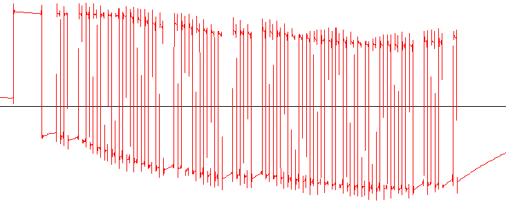
Next day I made a simple circuit to detected IR pulses. I used a 555 timer as a schmitt trigger with an IR photodiode detecting the IR. A cmos gate, opamp or comparitor would have served equally well. I had a visible led at the output and also fed the signal into my soundblaster card. I used wave-studio which came with the SB card to capture the data stream @ 48kHz. The wave file is here - pana-remote.wav. The carrier is supressed by the SB input filters but the data stream is clearly visible.

By
recording the data stream coming from the remote (the one that
came with the VCR) I confirmed the data I had was correct. However
my remote had a "T" period around 440 uSec and the start
bit timing was way out too.

Here
is a more detailed image of the start bits followed by a zero bit,
a one bit and then lots of zeros.
I recorded the data
stream from my circuit and the timing was spot on - but I had one
extra bit at the end. I fixed this and my program worked. This
would suggest the timing is not critical and there's no reason why
it should be, the data stream is pretty much self clocking an
*could* cope with huge speed variations if the detector designed
right. The modulation frequency is an other matter this could be a
narrow band filter but then again it may not be. Being in a
minimalist mood I went back to using the internal RC oscillator
and it work first time so I haven't check the timing any further.
A problem with the system is there is no way I know of to place the VCR in a know state. In normal use you can see what it's doing. But there is no easy way for the micro to detect what the VCR is up to. There is also no way to put the VCR in totally know state. The problem stems from the many controls which toggle a function - for example sending the "input select" code just changes the input from tuner to aux or visa versa but leave you none the wiser as to which input is selected. So to be triggered by the intruder the VCR has to be ON, not recording and not in timer-record mode. It's quite possible other control codes exist that we don't know about.
The input select problem can be gotten around because sending the VCR a channel code (as in TV channel) puts the VCR into a TV/tuner mode. So my record sequence consists of CHAN1,INPUT-SELECT and RECORD codes.
Originally I sent each code once with a delay between codes and found it the be unreliable. The real remote doesn't just send a code once, it keeps sending the code as long as the button is pressed.
Repeating each code 4 times worked well, repeating 10 times didn't work well as the input select would often toggle more than once - I'm not sure why. Anyhow I'm back to 4 repeats and it hasn't missed a beat since. Now I have lots of video of Eddie driving the car in and out or walking past with firewood - riveting stuff. There are even some shots in the dark to add that spooky X-files feel to it :)
The pump controller scanned a 2 by 3 switch matrix (6 switches) . I modified to code to only read 2 switches and freed up 2 port lines in the process. One of these (probably both next version) goes high when recording. This is optionally to turn the IR light source on. It could also be used to sound a buzzer. The PIR unit has a simple switch contact which interfaced easily to the modified pump switch scanning routine. Details about the switch interface and software will be available when I finish the pump project and its web page.
I'm fairly happy with my controller but the camera is another matter.
Download the program source here Ir1meg.asm