The opthalmatron (David
Atchison) - The is an antique piece of equipment for measuring
the power of a human lens. The opthalmatron was modified by my
predecessor to do continuous recording instead of a single shot
mode. The opthalmatron needed much attention to keep it alive
long enough to complete a series of experiments it was used for.
LED Controller (Andrew
Carkeet). A HC11 based device for flashing two LEDs with a user
downloaded wave shape (usually a Gaussian). The time delay
between to two flashes was accurately controlled.
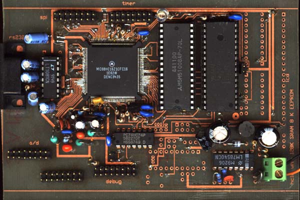
Chart recorder replacement.
(Chris Wildsoet). A HC16 based signal generator, and data logger
which interfaced with and eye-tracker. This is used in prac
classes. The device has a graphical LCD running a simple GUI I
wrote. The data which was logged could be printed out on a cheap
dot matrix printer.
Eye tracker (Chris Wildsoet).
A replacement for a dead eye tracking unit. This uses a IR LED
flashing at 3Khz (I think) and a pair of IR detectors plus
associated filters and amplifiers to detect the direction of
gaze of a human eyeball by detecting the reflected light off the
iris.
Stretcher (Chris Wildsoet). A
HC11 based controller which stretched a piece of tissue using a
stepper motor screw drive and measured and logged the tension at
each step using an FT-03 force transducer.
Eye track ( David Atchison). I
interfaced a commercial eye tracker to a PC and also interface
the PC to an auto-refractor. PC software was in turbo-vision.
Traffic Light simulator (David
Atchison). A HC11 based controller which simulated traffic
lights measured subject re-action times to different colors and
brightness. This was done by building two small filter turrets
and back lighting them with HC11 controller lamps. PC software
was in turbo-vision.
Interferometer (David
Atchison). A HC11 based controller to automate stimulus
presentation on a interferometer. This allowed a number of
visual acuity tasks and contrast sensitivity task to be
performed. We were trying to match these tasks with similar ones
based on a VSG (see below). PC software was in Delphi.
VSG (David Atchison). The VSG
(visual stimulus generator) is a PC based card for generating
gratings and other visual stimulus and a monitor. PC software
was in Delphi.
Car timer. (Joanne Wood) A
laptop PC based re-action timer for test drivers on a test
track. The PC turns on one of 5 possible lamps when the
researcher pushed a button and then measures the time taken for
the driver to press the brake pedal.
Light house (Joanne Wood). A
HC11 based controller which controlled the speed of a rotating
mirror and also fired and electric shutter. This is for testing
dynamic visual acuity by projecting moving image on a screen.
That is - to test a persons ability to identify moving targets.
Merry-go-round. (Katrina
Scmid). A HC11 controlled optokinetic drum. That is a drum which
rotated in a particular manner and is stripped on the inside.
Something to make chickens dizzy.
Stereo Acuity tester. (Michael
Collins) A HC11 based controller to move some pins under PC
control. This is to test depth perception. PC software was in
Delphi.
Video Attenuator (Neal Strang)
- a resistive attenuator for mixing RGB video outputs into a
high resolution monochrome signal.
UV dose meter (Tom). A HC11
based UV dose meter which has two parts to it. One was a
matchbox sized unit which was worn like a badge. This was
experimentally worn by professional arc welders. It measures UV
dose, total arc time and the number of arc strikes. The second
part plugged into the first and had a LCD display and switches
for reading out the dose measurement and resetting the device.
Double flash apparatus (Brain
Brown). A HC11 based controller for presenting accurately time
pulses and pairs of pulse from a LED. It also rotates a stepper
mounted neutral density wheel.
Stiles-Crawford apparatus
(David Atchison) A HC11 based controller for measuring the
Stile-Crawford effect for images projected into different parts
of the eye. The optical set up in quite complicated. The
controller moves a stepper driven xy stage and controls a pair
of LEDs - one of these LEDs can be varied in brightness over a
range of 10,000 to 1. PC software was in Delphi.
Vernier Alignment apparatus (David Atchison) A HC11 based
controller for measuring vernier alignment for images projected
into different parts of the eye. It controls the same xy stage
as the Stiles-Crawford setup plus it lets the subject align a
spot on a CRO with a fixed target be using a joystick. PC
software was in Delphi.